
CNC Manual, Part 2: Setup & Workflow
Part 2 of the Velocity CNC router manual. Read Part 1 – Safety & PPE first if you haven’t.
Before You Start
Put on your PPE (safety glasses, hearing protection, hair tied back, no loose clothing) and confirm dust collection is on and clear before powering anything up.
1. Power On
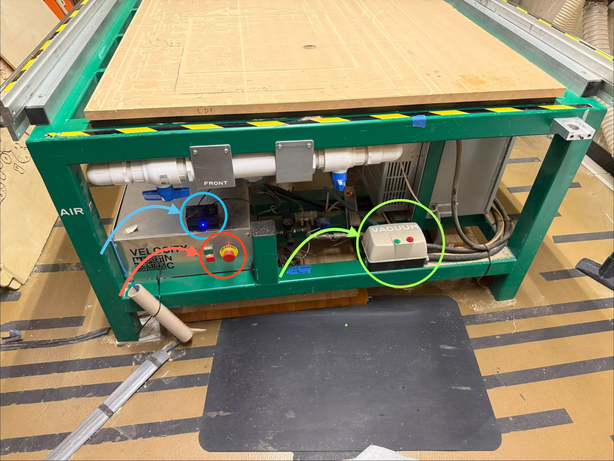
- Main power comes on at the wall disconnect, then the control PC, then the CNC12 software. The CNC controller, spindle status, and vacuum control switch are on the control box at the front-left of the table.
- Wait for CNC12 to fully load before touching any controls.
2. Home the Machine
Homing tells the control where the machine physically is. Every session starts with a home cycle – don’t skip it, and don’t assume yesterday’s position is still valid.
- Confirm the table is clear of tools, clamps, and material before homing – the machine will move through its full range.
- Run the home cycle from the CNC12 interface. All axes should complete without a fault.
3. Load and Secure Material
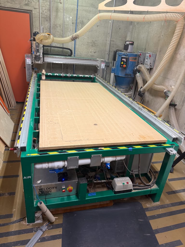
- Position stock on the table/spoilboard. This table uses vacuum hold-down: a plenum sits between the spoilboard and the vacuum table, sealing the surface so the vacuum pump can pull the material down.
- Make sure the material is fully secured before running anything – a shifting workpiece is one of the most common causes of a ruined job or a broken tool.
- Double-check clamps or fixtures aren’t in the path of the toolpath before you run the job.
Before starting the vacuum, confirm the plenum is fully seated over the vacuum table. If it’s shifted to the side like the photo below, dust bypasses the vacuum table entirely instead of being pulled through it.
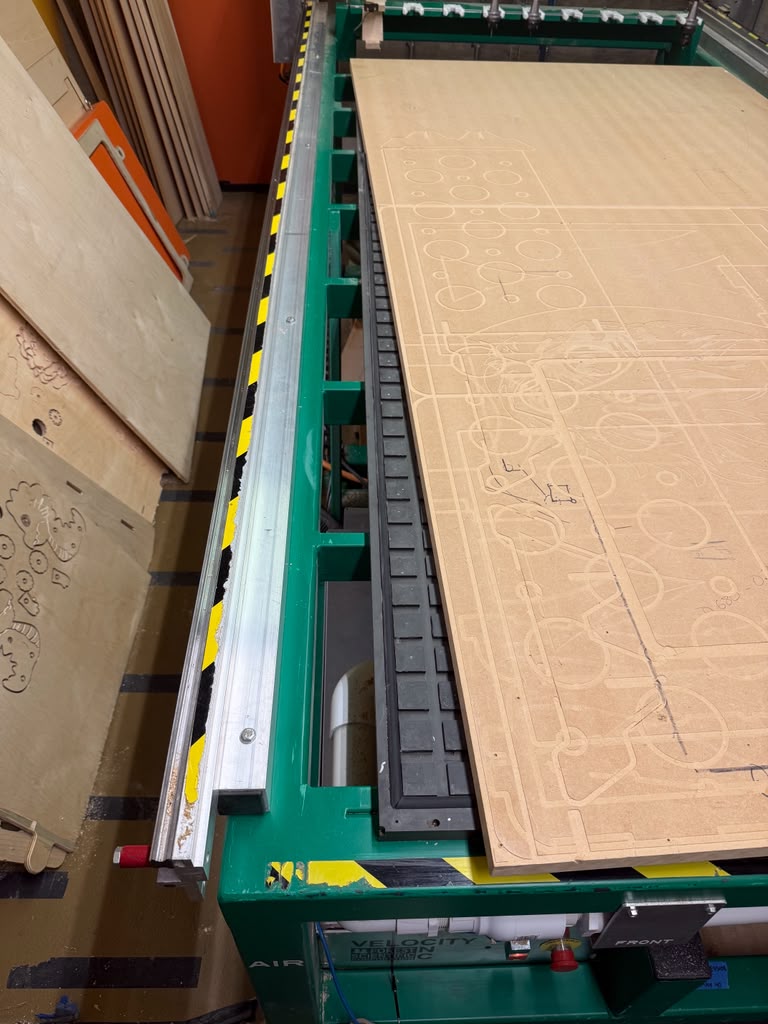 The plenum shifted off the vacuum table – dust would bypass the vacuum instead of being pulled through it. Always push it fully back into place before starting a job.
4. Zero the Work Coordinate System (WCS)
This machine has dedicated VCP (Virtual Control Panel) buttons for zeroing, built specifically for this table – see the VCP Skin & Macro Customization Guide for how they work internally.
- Zero X, Zero Y, Zero Z – jog to your part’s zero point (typically a corner of the stock) and press each button to set that axis to zero at the current position.
- WCS X0 Y0 – once zeroed, this button raises Z to a safe height and rapids back to your part zero. Use it to sanity-check your zero before running a job, and to return home between operations.
Always verify your zero visually before running – jog down slowly and confirm the tool is actually touching where you expect part zero to be, rather than trusting the display alone.
5. Warm Up the Spindle
Press the Spindle Warm-Up VCP button before every job, especially the first cut of the day. It ramps the spindle through six stages from 3,000 to 22,000 RPM in place, which protects the spindle bearings – running straight to full RPM on a cold spindle is hard on the machine.
Let the warm-up finish completely before starting your job.
6. Load and Check Your G-code
- Load your G-code file into CNC12.
- Run the toolpath in Graphics/backplot mode first – never run a new file at full speed without previewing it. Check that the toolpath matches what you expect and stays within your material and table bounds.
- Confirm the correct tool is loaded for the first operation.
7. Run the Job
- Stay in the room for the entire cut. Keep a hand near Feed Hold / E-stop, especially for the first pass of a new file.
- Press Cycle Start. Note: any VCP macro button press (including the zeroing and warm-up buttons above) also requires a Cycle Start to actually execute – pressing the button alone doesn’t run it.
- Watch the first plunge and first few passes closely. This is when a bad zero, a loose clamp, or a wrong tool shows up.
8. Shutdown
- Let the spindle spin down fully before leaving the area.
- Retract to a safe Z height and, if you’re the last job of the day, return to home.
- [Confirm this shop’s standard power-down order – reverse of power-on is typical: drives off, then CNC12, then PC, then main power if you’re closing the shop.]
- Clean the table and floor, and remove your material and fixtures.
Previous: Part 1 – Safety & PPE. Next: Part 3 – Software & CAM Basics.